


By Dave Porter, Technical and Customer Support at The Bonneville Shop
Establishing Ignition Timing
Converting to an Electronic Ignition
You have finally decided to convert your 1967 Triumph Bonneville to electronic ignition. The instructions tell you to remove the points plate and mechanical advance unit. Not to worry, once the old ignition parts are out of the way, you can start retrofitting your new modern ignition.
Once the rotor and stator plate are loosely fitted, you are instructed to connect all of the electrical wiring, carefully following the instructions. Then they mention setting the engine to the “full advance timing mark on compression”. What does this mean? You open up the factory workshop manual for more guidance, only to learn that the flywheel on your engine’s crankshaft has only one notch, indicating top dead center (TDC).
This is usually the point at which confusion sets in for the first-time electronic ignition installer. If you are able to read through the series of instructions from Sections B28-B31 in the 1963-1970 Factory Workshop Manual without any confusion, and with a complete grasp of what is being described, then you are probably a genius and will find this article remedial. For the rest of us, I am going to try to save some time by simplifying using a degree wheel to establish ignition timing.
Fully Advanced Timing Position
“If you are able to read through the series of instructions from Sections B28-B31 in the 1963-1970 Factory Workshop Manual without any confusion, and with a complete grasp of what is being described, then you are probably a genius and will find this article remedial.”
The early unit-construction Triumph 650cc engines employed a contact breaker ignition, housed in the timing cover, and driven by the exhaust camshaft. The Lucas 4CA points ignition was used through the 1967 model year and was problematic for tuners to set accurately, which makes these motorcycles ideal candidates for retrofitting an electronic ignition system.
For many years, the Boyer-Bransden was the industry standard for this endeavor, but there are more options now including Pazon, Vape, Tri-Spark, and Sparx. The set-up of these ignition kits is very similar from brand to brand, but they all have one thing in common- they have to be initially set with the engine in the fully advanced timing position, which in our example bike, the 1967 Triumph 650, is 38 degrees before top dead center (BTDC). This the position where the pistons are .415” from their highest point in the cylinder bores, and on the rise towards top dead center (TDC). The Timing Degree Wheel is employed to establish this engine position.
Using a Degree Wheel and TDC
To begin, place the motorcycle on the center stand, if equipped with one. If not, an alternative method of getting the rear wheel off the floor (or lift) must be used, such as using a portable jack, or even a sturdy milk crate to support the weight of the machine. Remove the spark plugs and shift the transmission to high gear.
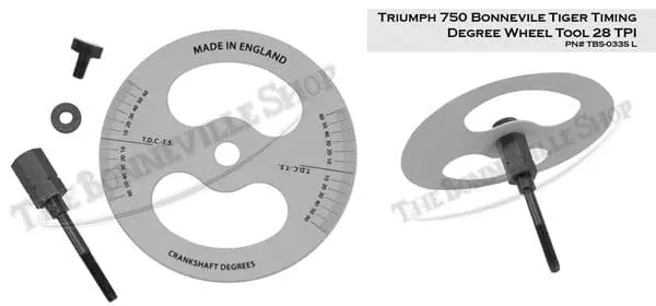
Now the rear wheel can be rotated to easily change the engine position. Now you can assemble your degree wheel and prepare to thread it into the end of the exhaust camshaft, which will be exposed, having already removed the points plate and mechanical advance unit. In the case of our example bike, the 1967 650 will have a ¼”-26 TPI threaded bore in the exhaust camshaft, provided the camshaft is the factory original cam. We offer the Timing Degree Wheel kit in (2) versions, the TBS-0335 E (with a ¼”-26 bolt), and a TBS-0335 L (with a ¼”-28 bolt). You will be using the earlier ¼”-26 bolt for this exercise.
The next step will be to remove the timing aperture plug from the crankcase, located just below the rear of the cylinder barrel, on top of the gearbox housing. Once the plug is removed, you will be able to see the crankshaft flywheel. With the aid of a small flashlight, you can peer into the hole and while slowly rotating the rear wheel, you will see the slot on the flywheel appear, then quickly disappear from sight. When the slot is again seen by very slowly rotating the wheel in either direction, you will have located TDC. Now is the time to talk about another essential tool, the Crankshaft Timing/Locking tool, which we offer under part number 60-0571.
Crankshaft Timing/Locking tool

Now that you have found TDC, you can thread the Crankshaft Timing/Locking tool into the aperture in the crankcase. The plunger will locate the slot in the flywheel and keep the TDC position from being disturbed while you move on to the next step. You will need to source a pointer as an indicator for the engine position, calibrated to the degree wheel. I have found a plain 14 or 15 gauge bicycle spoke, with a point ground onto the end, works well for this. The spoke can be bent to whatever position you need to line up with the edge of the degree wheel.
Once the correct pointer has been sourced and bent to suit the task at hand, it must be attached to the engine to make it stationary. You can use one of the timing cover screws to secure the pointer, by bending a loop in the end of the spoke wrapping it around under the screwhead. Since the TDC engine position has already been established, the degree wheel can be rotated on the mandrel to line up with your stationary pointer, then locked down with the knurled thumbscrew. The following picture shows the assembly in place, indicating TDC.

Timing Degree Wheel
The next task is to remove the loosely threaded bolt from the camshaft that retains the magnetic rotor from your electronic ignition kit. Now thread in the Timing Degree Wheel assembly. Once hand tight, the degree wheel can be rotated on the mandrel so that the pointer is aligned with the TDC mark on the degree wheel. Tighten the thumbscrew on the mandrel to fix the degree wheel in place.
At this point, remove the Crankshaft Timing/Locking Tool. You are now ready to turn the engine backwards 38 degrees by slowly rotating the rear wheel anti-clockwise until the degree wheel aligns with the pointer at the 38 degree mark on the scale. You have now located the full advance timing position of the crankshaft to set up your electronic ignition according to the manufacturer’s instructions.
If you have a piston stop tool, this would be the right time to thread it into one of the spark plug holes and adjust it to touch the top of the piston, preventing it from moving any further while you finalize the electronic ignition installation. Since the Timing Degree Wheel was only hand tightened, it should be able to be withdrawn without disturbing the engine position. Once the Timing Degree Wheel is out of the way, the center bolt can be refitted to secure the electronic ignition’s rotor.
“You have now located the full advance timing position of the crankshaft to set up your electronic ignition according to the manufacturer’s instructions.”

If you are performing the same electronic ignition installation on a 1969 or later Triumph 650 model, including some late 1968 models, you will likely not need a degree wheel, as the stock flywheels had an additional notch cut into them for establishing 38 degrees BTDC, however the 61-7022 Crankshaft Timing/Locking Tool will be needed to accurately establish engine position. As the transition to Unified threads was underway, the timing hole threads changed to a coarse UNF thread, necessitating the updated 61-7022 Crankshaft Timing/Locking Tool.

It is worth mentioning that both versions of our Timing Degree Wheel kits, TBS-0335 E and TBS-0335 L are intended for use on ignition timing through the camshaft, which spins at half-speed of the crankshaft. There are occasions when ignition timing is called for on a vintage Triumph with magneto or distributor ignition. I have a Crankshaft Degree wheel that was originally included on a page in the early unit-construction Triumph 350 &500 Factory Workshop Manual. I cut it out and pasted it onto a piece of cardboard. As you can see in the picture below, it is mounted directly onto the end of the crankshaft. I hope this article has been helpful and interesting, thanks for reading it.

Ignition Timing FAQs
What is the correct ignition timing for a 1967 Triumph Bonneville 650?
The full-advance ignition timing position for the 1967 Triumph Bonneville 650 in this guide is 38 degrees before top dead center (BTDC). This is the engine position used for the initial electronic ignition setup. Always confirm the specification against your motorcycle’s workshop manual and the instructions supplied with your ignition kit.
Why do I need a degree wheel to install electronic ignition on an early Triumph 650?
A degree wheel helps locate the full-advance ignition timing position when the flywheel only has a top dead center (TDC) notch. On the 1967 Triumph 650 described in the guide, the TDC notch does not identify the required 38-degree BTDC position. The degree wheel provides a reference for moving the engine from TDC to the correct initial timing position.
What do TDC and BTDC mean when setting motorcycle ignition timing?
TDC means “top dead center,” the point where a piston reaches its highest position in the cylinder. BTDC means “before top dead center” and identifies an engine position before the rising piston reaches TDC. In this guide, 38 degrees BTDC describes crankshaft position—not a distance measurement or an idle-speed setting.
Which degree wheel kit fits my Triumph’s exhaust camshaft?
The Bonneville Shop lists two camshaft-mounted timing degree wheel kits: TBS-0335 E, supplied with a ¼-inch–26 TPI bolt, and TBS-0335 L, supplied with a ¼-inch–28 TPI bolt. The guide’s 1967 Triumph 650 uses the ¼-inch–26 version if its original exhaust camshaft is still installed. Confirm your camshaft’s actual thread before ordering, especially on a rebuilt or modified engine.
Which crankshaft timing and locking tool do I need for my Triumph 650?
The guide uses crankshaft timing/locking tool 60-0571 for its 1967 Triumph 650 example. It identifies tool 61-7022 for later engines with the revised timing-aperture thread. Select the tool that matches your engine’s timing hole rather than assuming one tool fits every Triumph 650 model year.
How do I find top dead center on a classic Triumph 650?
For the engine described in the guide, remove the crankcase timing-aperture plug and slowly rotate the engine until the flywheel’s TDC notch appears through the opening. The correct crankshaft timing/locking tool then engages the notch to hold the engine while you align the degree wheel and stationary pointer. Remove the locking tool before rotating the engine again.
What tools do I need to establish ignition timing with a degree wheel?
The guide uses a compatible timing degree wheel kit, the correct crankshaft timing/locking tool, and a stationary pointer attached to the engine. It suggests a shaped bicycle spoke for the pointer. Preparation also includes securely supporting the motorcycle with the rear wheel raised, removing the spark plugs, and selecting high gear so the rear wheel can turn the engine.
Do 1969 and later Triumph 650 motorcycles need a degree wheel for ignition timing?
Not usually, if the original flywheel with its additional timing notch remains fitted. The guide explains that 1969 and later Triumph 650s, plus some late-1968 models, have a flywheel notch marking 38 degrees BTDC. That notch can establish the full-advance position using the appropriate 61-7022 timing/locking tool, without a degree wheel. Verify the components actually installed in your engine.
Can I use the same degree wheel on the camshaft and crankshaft?
Do not assume a camshaft timing degree wheel is interchangeable with a crankshaft degree wheel. The TBS-0335 E and TBS-0335 L kits described in the article are intended for camshaft-mounted ignition timing, and the camshaft turns at half crankshaft speed. The article shows a separate crankshaft-mounted degree wheel for other applications, including magneto or distributor ignition.
Does this ignition timing method work with Boyer, Pazon, and other electronic ignition kits?
The guide discusses Boyer-Bransden, Pazon, Vape, Tri-Spark, and Sparx electronic ignition systems. Establishing the specified full-advance engine position provides the starting reference for installation, but it does not replace the instructions for the individual kit. Follow your ignition manufacturer’s directions for wiring, rotor and stator alignment, and completing the timing setup.