By Mike Grage, Tech and Customer Support at The Bonneville Shop and British Iron
Carb Cleaning and Tuning
You might have noticed something, that those Keihin and Mikuni carburetors on your late model Triumph are not your grandpa’s Amal’s. But they are very similar in function to the Bing carbs Triumph used on your dad’s 1982 Bonneville Executive. Most of the time, a carb cleaning will cure any runability problems a motorcycle with stock CV carburetors is experiencing. Blocked fuel passages in the pilot circuit, and blocked air passages in the main circuit are the culprit for most carb problems. Occasionally a damaged carb body is to blame.
Either way a jeweler’s loupe or some high magnification glasses are very useful because the smallest scratch or smallest crack in the carb body in the wrong location can cause gigantic problems. However, if you are changing to a high flow air filter, changing the exhaust, or making any performance modifications you will need to re-adjust and re-jet your carburetors. Since much of the art of overhauling and tuning CV carburetors has been lost to history and they can be a pain to deal with, I’m going to make this guide as comprehensive as possible.
The most important thing to mention is that the carburetors only need to be separated to replace the butterfly seals or the fuel pipe and vent pipe o-rings. Otherwise, this is an extra time consuming step.
Float Bowl/Fuel System Ventilation:
One issue that can affect float level is clogged or blocked float bowl vents. The hoses attached to the tees at the top of the carburetor bodies with hoses the go to the back of the engine cases and to the ground on 49-state and international models need to be free and clear. Any blockage or kinks in these hoses or tees will prevent fuel from flowing through the jets the same way holding your finger over the end of a drinking straw will hold your beverage in the straw when you pull it out of your fountain drink cup. A clogged fuel tank vent or clogged fuel cap vent will cause the same issue.
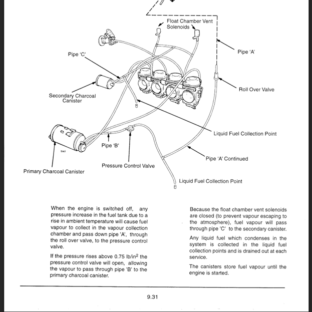
California models of this era (and all ’08-on motorcycles) have an evaporative loss system, a failure in this system can cause ventilation problems for the fuel tank and float bowls. These bikes have float chamber solenoids that close the float bowl vents when the bike is not running. Plus, they have a pressure control valve that regulates fuel tank pressure and ventilation. Either one failing to open will cause a no start or poor running condition.
Float Bowl Fuel Level:
Checking to make sure the fuel level in the float bowl is correct should be the first step in any carburetor diagnostic or tuning procedure. The process for checking the float level with the carbs installed is rather easy. Triumph supplied dealers with part number 3880125-T0301 to check the float level with Keihin carbs installed, that tool is just a clear hose with .5mm markings. I always use a battery vent hose because it’s the same thing, and I use machinist rule the for measurements the markings on the Triumph tool provides.
To check it this way, you attach the hose the float bowl drain nipple. Loosen the float bowl drain screw enough to let fuel flow out the nipple but not leak past the threads. Hold it up next to the carb so it will act as a level, then turn the petcock to prime (marked as Pri on the petcock). You will need to turn the key on with California models to engage the float bowl vent solenoid. The Mikuni BST carbs will need an adaptor like Triumph part number 3880120-T0301 to do this since they usually lack a drain screw that functions the same way.
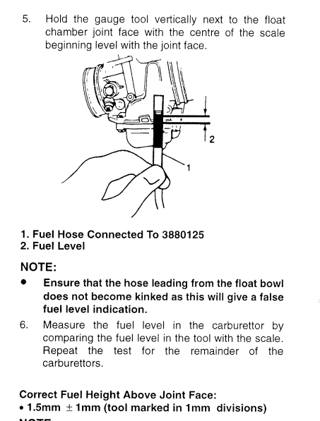
The fuel in the tube should be 1.5mm (+/ 1 mm) above the gasket surface. That’s the equivalent of 1/16”-3/32” above the gasket surface as seen in the above illustration.
The factory service manual tells you to remove the carbs, make the adjustment by bending the float needle tab, then reinstall and follow the above instructions. With the carbs off and float bowl removed you can use a machinist rule to make a precise adjustment. To make this even simpler, K&L Supply makes a great float level gauge (35-9123). A small flat blade screwdriver is the best tool to use for adjusting the tab.
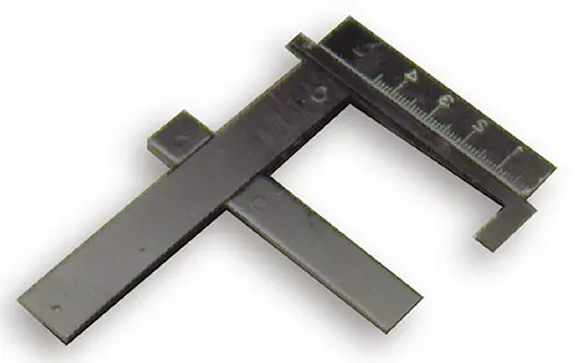
The float needle and seat in the Mikuni BST carburetors is easily replaced. However, they are not replaceable in the Keihin CVK carbs. It is not the end of the project if you replace the float needle in a Keihin CVK and it still leaks. You can clean up the seat with a cotton swab and some 220+ grit Clover lapping compound, just make sure to thoroughly clean out all of the lapping compound.
Pilot (idle) circuit:
The components in this circuit consist of carb body passages, pilot jet, and idle mixture screw. Some CV carburetor will have an air cut off valve to eliminate deceleration backfiring, similar to what is used on the ’01-’09 Bonneville.
The factory service manual does not provide much information on this circuit. The reason why dates back to the 1983 EPA rule requiring tamper proof idle mixture adjustment screws. Carburetor companies started blocking them off with a solder plug that is easily removed with a drill bit. Dealer technicians are supposed to replace the solder plugs after making adjustments, but rarely do so because carburetors will not stay clean forever. The service manual gives a stern warning about this.
The reason for the caution about muffler probing emissions testing is the same reason for the plugs in headers. Those plugs in the header are adaptor ports for an exhaust gas analyzer so the dealer technician can get the fuel mixture spot on the 1% CO for USA models during new bike delivery process. With the proper equipment those ports are very useful for speed tuning. The procedure for adjusting the mixture screws without an EGA machine should be done during the carburetor synchronization process, that will be covered a little later in the blog.
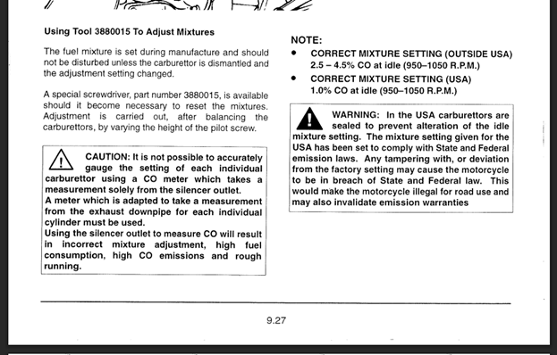
Normally when overhauling/cleaning EPA compliant CV carburetors, you will need to drill out the solder plugs that seal off the idle mixture screws. However, when working on a 49-state Triumph made between 1996-2008 there is a very good chance the plugs were removed during the make ready process and never replaced. You will need a special d shaped bit like what is included in the Motion Pro hex driver set sold on Modern British Iron to remove or adjust the mixture screws.
The replacement mixture screws Modern British Iron provides have slotted heads instead of the D shaped. The mixture screw assemblies for both Mikuni BST and Keihin CVK carbs consist of the screw, a spring, a washer, and an o-ring. A bad or missing o-ring can cause a lean condition and make it impossible to properly tune.
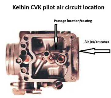
For this circuit to function properly the air passage from the intake side of the circuit to the jet holder must be clean and clear. Spray some carb cleaner into the air passage/air jet paying close attention to make sure it is flowing freely into the jet holder. Follow it up with some compressed air to make sure it’s clear.
On a Keihin CVK the air inlet is on the air cleaner side of the venturi. Sometimes there is a removable air jet, there’s no reason to remove or replace the air jet because they rarely get clogged with old fuel.
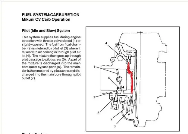
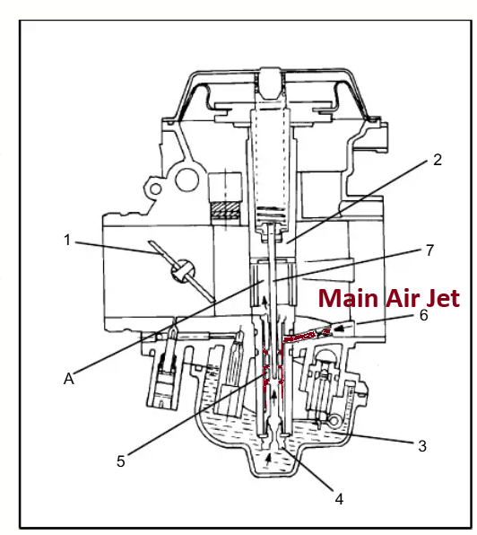
The Mikuni BST air jet is located under the slide diaphragm and cover on the top of the carburetor. Using a diagram in place of a picture makes the circuit easier to explain the location. Otherwise, it would take 3 or more photos to show the location and route. There is no reason to remove or replace the air jet, unless you are doing some serious engine modifications.
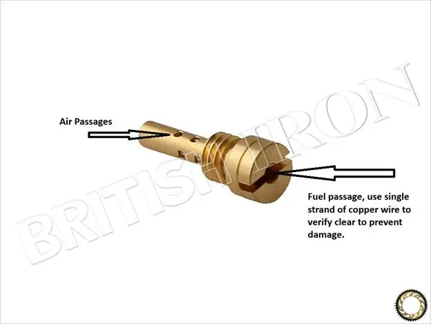
The air and fuel passages on the Keihin pilot jet must also be clean and clear. It is recommended to strip a length of copper wire and use a single strand to make sure the fuel passage is clear. Tip cleaners can easily damage the jet and cause erratic fuel flow, and a running condition that will drive a man insane. After poking the wire through, spray some carb cleaner through it and make sure it’s a uniform amount coming out the other end. Follow that up with some compressed air. Pictured below is a jet for Keihin carburetors.
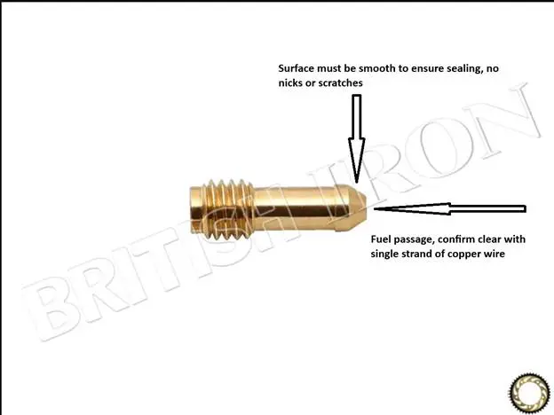
Mikuni pilot jets do not have air holes on the side. For these you need to use the copper wire to make sure the fuel passage is clear. Use carb cleaner to make sure it has a uniform flow, and follow it up with compressed air. On the opposite end of the jet there is a taper, closely inspect this taper for any damage. Check the seat in the carb body to make sure the jet will properly seat in the carb body. If the taper is not sealing correctly, you will have a rich condition with an unstable idle.
Next you need to make sure the passage from the pilot jet to the mixture screw holder, idle fuel port, and transfer ports are clear. This procedure is the same for all Keihin CVK and Mikuni BST carbs. Spray some carb cleaner into the mixture screw hole, make sure you get a good flow through the pilot jet holder. Follow that up with some compressed air.
Do another spray into the mixture screw holder with the throttle open while covering the mixture screw port in the venturi with your finger. Pay attention to the flow that comes out of the 3-4 holes in a diamond formation just under the throttle butterfly. These are the transfer ports. The transfer ports are there to transfer the fuel flow from the pilot circuit to the jet needle/midrange circuit. If you’ve ever had a motorcycle with CV carbs that stumbles when it comes off idle, it’s usually due to the transfer ports being clogged up with residue from dried fuel.
Most of what I’ve written up until this point is either missing or extremely vague in the majority of service manuals for motorcycle produced after 1977 because the EPA does not want the consumer/end user to be able to adjust the idle fuel mixture or repair that system in the carburetor. You can read more about this in the Importance of Right to Repair Legislation blog I wrote in 2022.
Keihin Needle Jet/Jet Needle/Emulsion Tube
The jet needle and needle jet work with the slide to control the fuel flow in the mid-range. This is adjusted by moving the jet needle up (richer) or down (leaner). However, to make them function correctly air passages in the carb body and emulsion tube must be clean and clear.
To remove the needle jet and emulsion tube from a Keihin CVK carburetor you will need to remove the slide/jet needle and float bowl. For Keihin the emulsion tube is also referred to as the main jet holder. After removing the main jet you will need a 10mm 6-point socket to remove the emulsion tube. Then the needle jet is held in place by the jet holder, and is removed from the float bowl side. Most of the time you will have to use a decent size pin punch (big enough not to damage the needle jet) to drive it out of the carb body.
There are air holes on the side of the emulsion tube (jet holder) that must be clean and clear. Use the strand of copper wire to make sure these are clear. Then hold your finger over one end and use some carb cleaner to make sure they all have a uniform flow. Follow that up with a blast of compressed air. The easy way to do this is with the main jet screwed in the emulsion tube.

The main air jet/passage in the Keihin CVK carb body is right next to the pilot jet air passage. Make sure this air passage is clean and clear with carb cleaner, and a blast of compressed air.
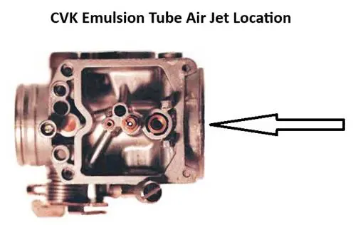
One issue I have noticed over the years happens when the emulsion tube/jet holder in Keihin CVK’s are over tightened. This will bend the emulsion tube and make it useless. This tends to result in a rich running condition.
Mikuni BST Needle Jet/Emulsion Tube/Main Jet Holder
The needle jet and emulsion tube are one piece in the Mikuni BST carburetors. In order to remove and clean it you will need to remove the slide cover, slide, and float bowl. Then you will need to remove the main jet and washer. The main jet washer can get stuck with old fuel. A pic will pop it out fairly easy. Then the needle jet/emulsion tube can be removed by pushing it into the venturi and out through where the slide cover sits.
We need to make sure the air passages are clean and clear by using a strand of copper wire. Then sealing off the needle jet with a finger and using carb cleaner to make sure there is an even flow through all the air holes, and we finish it off with a blast of compressed air. Having the main jet screwed into the emulsion tube will make the carb cleaner and flow check less messy.
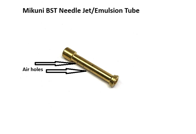
The main air jet/air inlet for the emulsion tube is located on the airbox side of the venturi, straight in front of the jet needle/needle jet. This passage should be sprayed with carb cleaner and given a blast of compressed air. The main air jet circuit is colored in red in the diagram below.
Jet Needle, Slide and Diaphragm
When inspecting the slides it is important to make sure they move smoothly through their full range. Make sure there are no pin holes or tears in the diaphragm, make sure there is no visible light shining through. Raise the slide all the way up and cover the vent port on the front of the carb, and make sure it stays up until you unblock the vent. Replace the diaphragm if there are any holes or tears, you can’t fix them and make them work properly. The hole in front of the jet needle should be unobstructed. And the jet needle should be clean with no nicks or scratches; those will disrupt the fuel flow.
Choke/Enricher
The last thing to check before reassembling the float bowls are the choke circuits. Spray carb cleaner in the choke jet and air passage and follow that up with a shot of compressed air. It is a good idea to check this circuit for leaks. The easy way to do this is to seat the choke plunger, then spray some carb cleaner into the fuel pickup tube in the float bowl, and the air passage on the airbox side of the venturi.
Synchronization & Adjusting Idle Fuel Mixture:
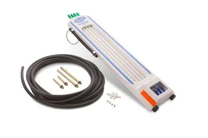
When reassembling the carburetors you should have be able to see the same amount of light visible around each throttle butterfly, what I call a bench sync. The mixture screws should be at 1.5-2 turns out. Connect a remote fuel bottle after installing the carburetors and connecting the airbox. Next you need to connect a carburetor synchronization tool. Personally, I prefer a manometer type set up and my favorite has always been made by Motion Pro.
The throttle synchronization adjustment screws are located between the carburetors and are circled in red in the photo below.
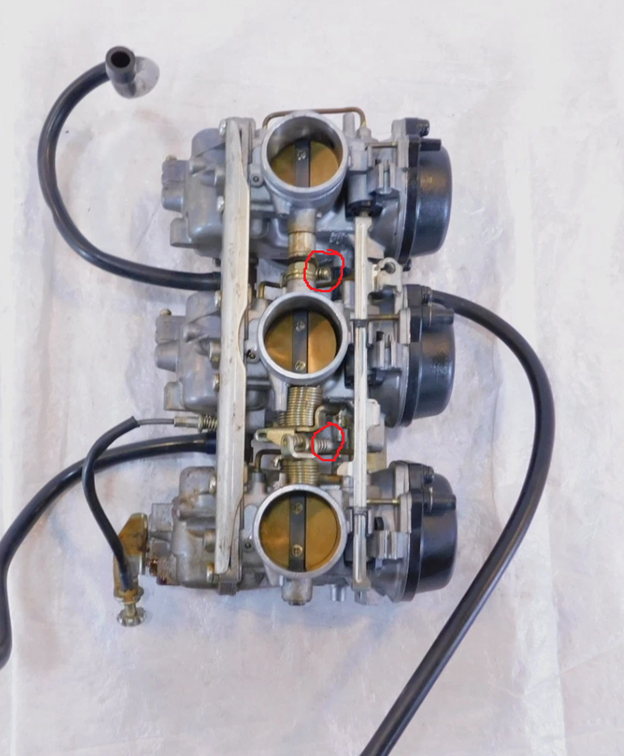
After the engine is started, warmed up, and at 1,000 RPM idle the first mixture screw to adjust will be on the master carburetor (center cylinder on triples, #3 on four cylinders). Turn the screw slowly in or out in small steps until the reading on the carb sticks is as stable as you can get it and the RPMs increase. Then adjust the idle, give it a few revs, and repeat for cylinders 1 and 3.
During this process it is important to make sure the vacuum readings on all 3 cylinders are even and within 130-150mm Hg (5-6 inches Hg). When the mixture screws are properly adjusted the engine should smoothly rev up into the middle of the RPM range.
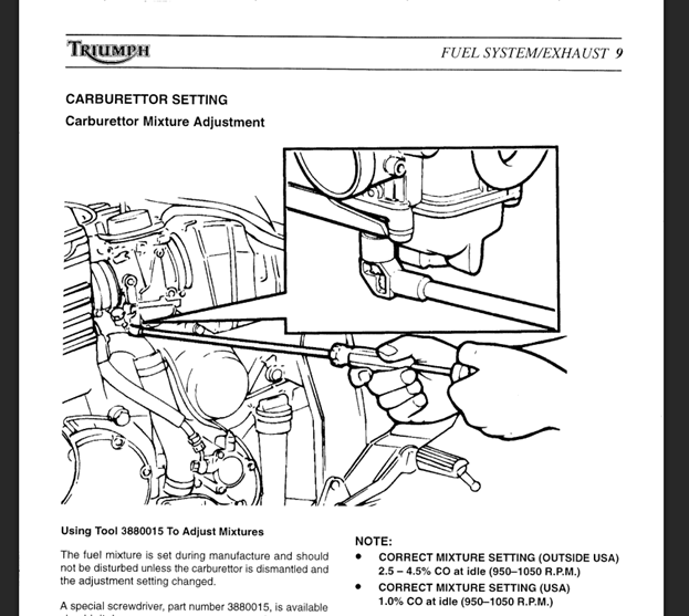
It may take several adjustments of the sync screws and mixture screws to get the idle to stabilize. So be prepared to rinse and repeat a few times.
Main Jet Tuning
With liquid cooled engines it is necessary to get a stable idle at normal operating temperature before any jetting changes can be made. The next step will be determining if the main jet is the correct size. The best method to do this the old-fashioned plug chop. You will need to find a road where you can ride the bike at full throttle in 2nd or 3rd gear for a couple of minutes without exceeding the speed limit.
After finding the road some new spark plugs will need to be installed. Then ride at full throttle for 2-3 minutes, pull in the clutch, shut the engine off and coast to a stop. Then pull the spark plug and check the color. The goal is the spark plug labeled as “Best” in the photo below.
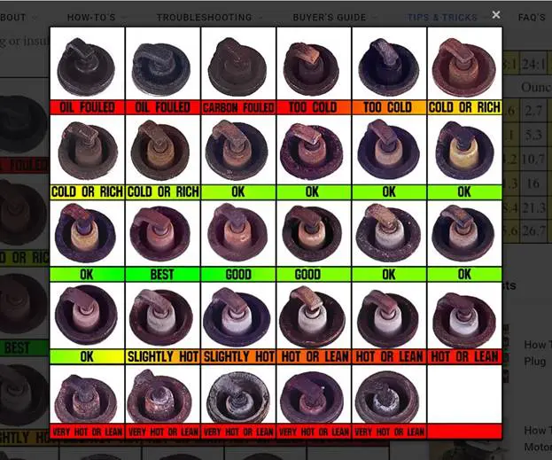
You will need to remove the carbs and float bowls to change the main jet. There should be no reason to make a mixture screw adjustment afterwards, but it is a good ideal to check the synchronization every time the carbs are put back on the bike. If the main jet is changed, you should perform another ‘plug chop’ to make sure you didn’t go too small or large.
Mid-Range Tuning
In order to make a full determination if we have the correct jet needle taper there will be three plug chops. The first thing that needs to be done is to mark the throttle grip and housing at 1/4, 1/2, and 3/4 throttle. First plug chop will be at half throttle to determine if the jet needle is in the right position. Lean will require raising the jet needle, rich means it needs to be lowered. The stock jet needles are fixed so all that can be done is raising them with small washers. Aftermarket jet needles like the ones Dynojet includes in their kits can be adjusted in up 5 different positions.
After that the 3/4 throttle plug chop, and then the 1/4 throttle plug chop to determine if a jet needle with a different taper is needed. Purchasing a Dynojet kit will generally have the best jet needle taper with 3-5 position adjustability.
Final Thoughts
Most people hate messing with CV carburetors because they can be very finicky and service manuals try to exclude information on the pilot circuit in an effort to play nice with the EPA. In the 1990’s the majority of the work I did during the springtime was carburetor cleanings on bikes that were parked during the winter with fuel in the float bowls. Float bowls should be drained before letting your motorcycle sit for any period of time more than 3 weeks because it doesn’t take much to clog up the pilot jet or emulsion tube air holes.
When Triumph shipped new motorcycles to the USA from 1996-2002 they would test run the bike and then crate it up without draining the carburetors. So, we had to do carb cleaning as part of the make-ready process and use those funny looking exhaust ports to get the mixture right before delivering to the customer. If you have followed this guide and have any questions, or a problem not covered, give us a call.

